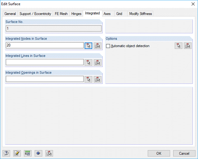
In a model, the member end is located on the shell of a pipe. Why is the calculation terminated with a message that the model is not sufficiently supported?
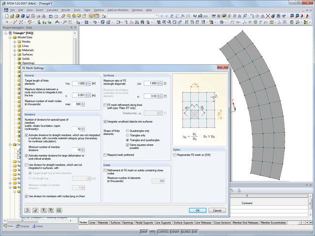
Is it possible to align the FE mesh manually in RFEM?In my example, there are "rigid" triangular elements at the edge, where quadrangular elements would be more realistic.
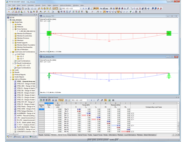
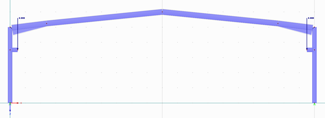
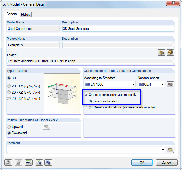
For a steel frame, I have manually created 20 load combinations with partial safety factors. However, the deformations should be determined without the factors. For this, I proceed as follows:
I copy each CO individually (several COs cannot be copied at the same time).
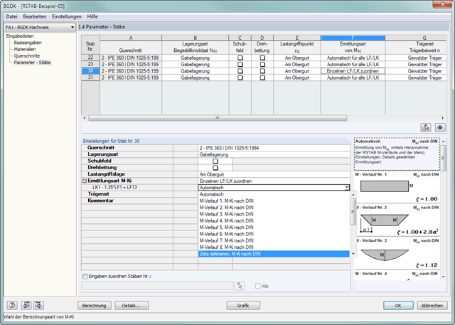
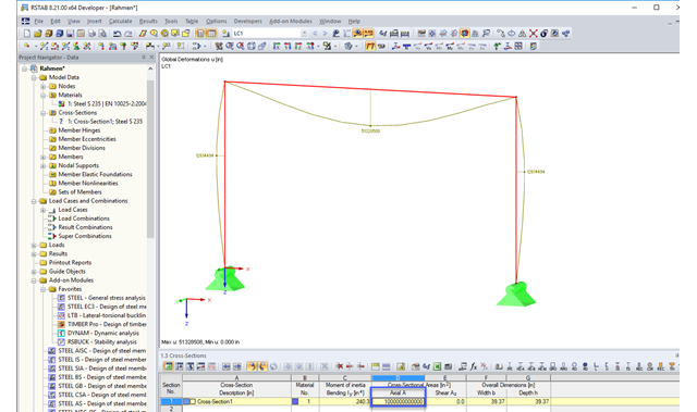
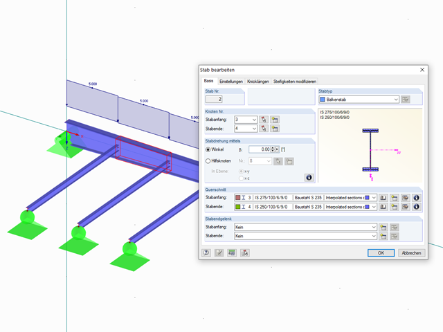
Is it possible to divide a tapered member in such a way that the interpolated cross-section is determined automatically at the division point? Is it possible to change the cross-section of a tapered set of members by changing the cross-section height on a member (start, middle, or end of the set of members) and then automatically determine the new cross-section heights for the other members?
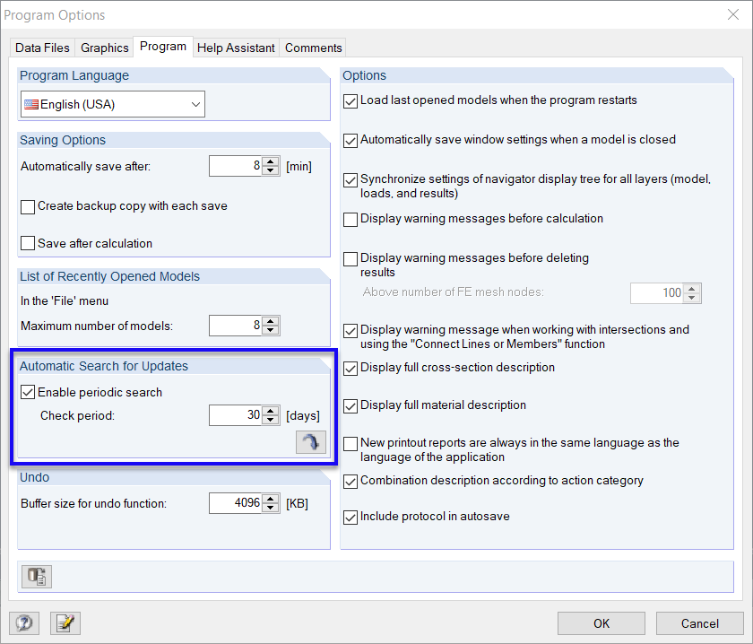
So far, I have been informed of new versions by your newsletter. It would be nice if the program checks and searches for updates automatically, at regular intervals.